
Map each size to its die
Place the approved CC/CU drawings into the three quoted bands. Flag widths and hole layouts between bands for a written custom-tool review.
CC/CU framing-profile production with a documented 75–200 mm overall web range; confirm the separate punch-die bands against each approved drawing. The final tooling, layout and guaranteed output are confirmed after we review your profile drawing and production target.
For the general light steel framing machine selection, compare member drawings, tool coverage and the production schedule before choosing this model. A CC/CU section label does not prove structural suitability or compatibility with every drywall or ceiling profile. For a drywall stud-and-track order, use the stud and track drawing review.
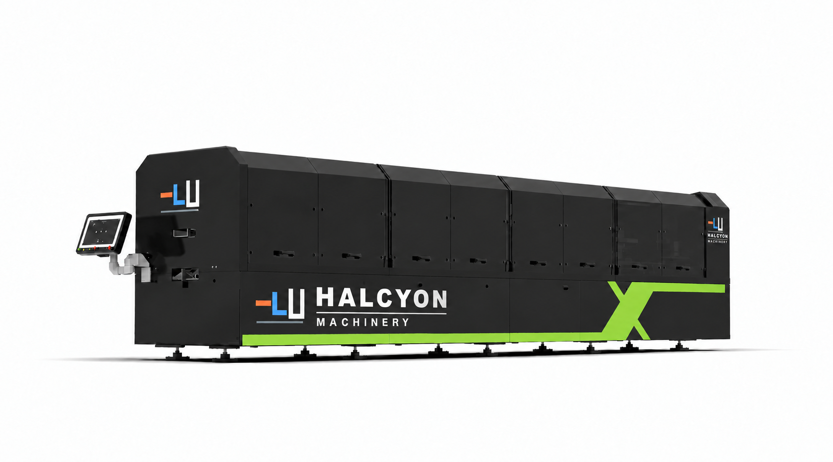
Reference configuration. Final machine follows the signed technical agreement.
The factory technical standard describes a 75–200 mm overall web range but separately lists standard punch-die bands of 75–96, 138–159 and 180–200 mm. A web width inside the overall range does not by itself prove the standard dies cover its holes.
Place the approved CC/CU drawings into the three quoted bands. Flag widths and hole layouts between bands for a written custom-tool review.
Run from a smaller to a larger section and back. Record software input, powered adjustments, any tool change and first acceptable parts.
Check service holes, connection holes, notches and cut features against each drawing; the same nominal web width may use different details.
Time a representative order with its actual punches, lengths and changeovers. Do not use the published high-speed figure as guaranteed shift output.
A flexible platform for three principal CFS width bands within a 75-200 mm total web range.
Speed note: punching, marking, cutting and part handling determine finished-member output.
The proposal defines every station, interface, production assumption and acceptance checkpoint.
We provide the current machine layout, component list, sample profile and test plan for the exact quotation.
Source: the factory's HSK-2000 technical standard supplied to Halcyon; review updated 27 September 2026. The offered revision and final tool list must be confirmed in writing.
Record the target web, flange and lip dimensions and the saved settings for each approved member.
List the three standard die bands and price any required out-of-band size as a separate confirmed scope.
Specify head and tail cuts, web or flange holes, service openings and any swage or notch by drawing revision.
Keep the setup log and measured first-off pieces for both directions of the size change.
Confirm run-out length, marking and part identification against the proposed production schedule.
Agree coil, sample count, dimensions, hole datum, tolerances and a complete-line timed run before production.
CC/CU framing-profile production with a documented 75–200 mm overall web range; confirm the separate punch-die bands against each approved drawing.
No. The supplied standard lists three included die bands. Ask for a written tool review and quotation for any width or hole layout outside them.
A witnessed two-direction trial showing inputs, powered and manual steps, elapsed time and measured first-off parts. A catalogue automation label is not enough.
Send every CC/CU drawing, steel grade, thickness range, hole and cut schedule, weekly size mix and target completed-part output.
We will confirm the suitable model, process route, line modules and the values that can be guaranteed for your material.