
By Halcyon Machinery · Technical content review · Updated
Specify the exit support from the longest accepted part, its profile drawing and the way operators will remove it. A line demonstration should show the cut part supported from the cut station through transfer, with the final profile checked after removal. A catalogue photograph or a nominal line speed cannot show that this works for your part.
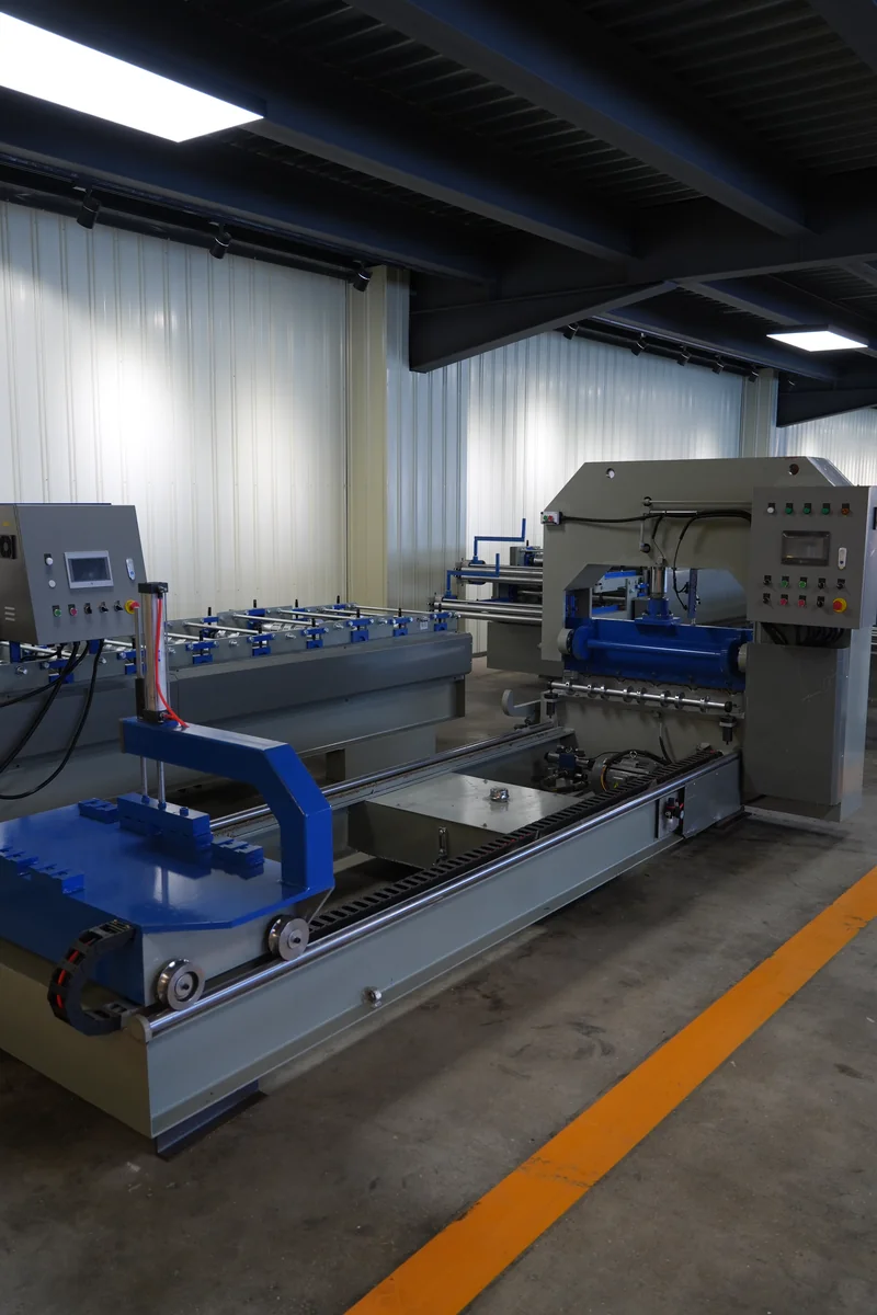
Start from the longest part, not the table
A short profile may leave the line cleanly while a longer one behaves differently. The question is not whether a runout table exists but whether its usable length, roller positions, transfer method and operator access match the part to be made. Ask the supplier to mark the support points on the proposed layout and show where the cut piece goes next: manual lifting, a stacker or another handling station. The answer may change with profile geometry and target output.
What to supply and agree for the trial
Provide the approved profile drawing, steel grade, thickness range, punching layout, target cut lengths and target output, and agree the material and length for the witnessed sample. Record the part as it exits, straight after cutting and after transfer, then compare it with the drawing for length, section geometry and visible handling damage. For a punched profile, check the hole layout is still usable after handling. Acceptance tolerances come from the drawing or purchase specification; this article sets no universal tolerance.
Longest-part trial record
Use the same drawing and coil specification when comparing suppliers, and leave the right-hand column blank until the witnessed run.
| Checkpoint | Agree before the run | Record from the witnessed run |
|---|---|---|
| Part and material | Drawing revision, steel grade, thickness and longest required cut length | Coil identification, measured cut length and labeled sample ID |
| Exit support | Runout layout, usable support length and positions that can be adjusted | Photos or video showing support from the cutter to the transfer point |
| Transfer route | Manual removal, table or stacker; operator position and stop/clear method | Observed transfer steps, intervention and any catching or surface damage |
| Finished sample | Drawing-based length, section and hole-location checks | Measured values on the identified part after transfer, with pass/fail against the agreed drawing |
Operator access and clearing the line
Ask who stops and clears the line if a part catches or fails to transfer, and confirm the reach and guarded-access arrangement for the actual layout before sign-off. A neat demonstration at a shorter length is no substitute for a test at the longest agreed length.
Four questions for the supplier
- Which maximum part length was actually demonstrated?
- Where does the operator stand during removal?
- Which support positions change for another profile?
- What drawings and sample records come with the proposed line?
Frequently asked questions
Is a roller table alone enough?
Not necessarily. The support and onward handling must be considered as one path for the approved part.
Can a video prove straightness?
Video helps show transfer behaviour, but dimensional acceptance still needs a measured sample and recorded drawing revision.
Related equipment and next step
For equipment selection, see the purlin machine page and factory layout guide. Send Halcyon your drawing, steel grade, thickness range, punching layout, longest cut length and target output to request a configuration-specific handling review through the contact form.
Send your drawing for a technical review